
Network Media – Connecting Communication
The Physical layer is concerned with network media and signaling. This layer produces the representation and groupings of bits as voltages, radio frequencies, or light pulses. Various standards organizations have contributed to the definition of the physical, electrical, and mechanical properties of the media available for different data communications. These specifications guarantee that cables and connectors will function as anticipated with different Data Link layer implementations.
As an example, standards for copper media are defined for the:
- Type of copper cabling used
- Bandwidth of the communication
- Type of connectors used
- Pin out and color codes of connections to the media
- Maximum distance of the media
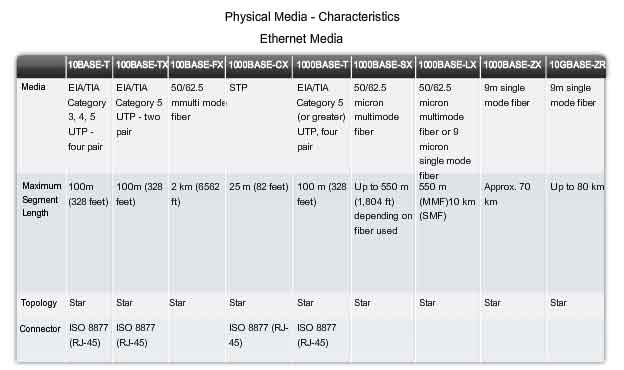
The figure shows some of the characteristics of networking media.
This section will also describe some of the important characteristics of commonly used copper, optical, and wireless media.
Copper Media
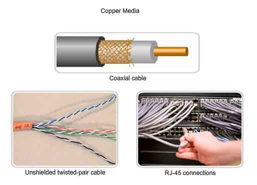
The most commonly used media for data communications is cabling that uses copper wires to signal data and control bits between network devices. Cabling used for data communications usually consists of a series of individual copper wires that form circuits dedicated to specific signaling purposes. Other types of copper cabling, known as coaxial cable, have a single conductor that runs through the center of the cable that is encased by, but insulated from, the other shield. The copper media type chosen is specified by the Physical layer standard required to link the Data Link layers of two or more network devices. These cables can be used to connect nodes on a LAN to intermediate devices, such as routers and switches. Cables are also used to connect WAN devices to a data services provider such as a telephone company. Each type of connection and the accompanying devices have cabling requirements stipulated by Physical layer standards. Networking media generally make use of modular jacks and plugs, which provide easy connection and disconnection. Also, a single type of physical connector may be used for multiple types of connections. For example, the RJ-45 connector is used widely in LANs with one type of media and in some WANs with another media type.
External Signal Interference
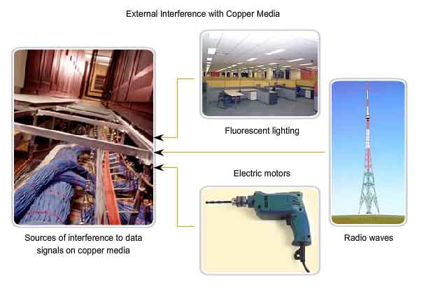
Data is transmitted on copper cables as electrical pulses. A detector in the network interface of a destination device must receive a signal that can be successfully decoded to match the signal sent. The timing and voltage values of these signals are susceptible to interference or “noise” from outside the communications system. These unwanted signals can distort and corrupt the data signals being carried by copper media. Radio waves and electromagnetic devices such as fluorescent lights, electric motors, and other devices are potential sources of noise.
Cable types with shielding or twisting of the pairs of wires are designed to minimize signal degradation due to electronic noise.
The susceptibility of copper cables to electronic noise can also be limited by:
- Selecting the cable type or category most suited to protect the data signals in a given networking environment
- Designing a cable infrastructure to avoid known and potential sources of interference in the building structure
- Using cabling techniques that include the proper handling and termination of the cables
Unshielded Twisted Pair (UTP) Cable
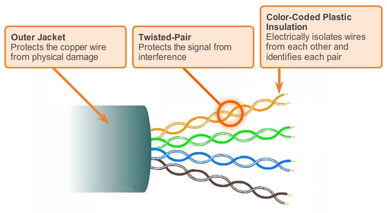
Unshielded twisted-pair (UTP) cabling, as it is used in Ethernet LANs, consists of four pairs of color-coded wires that have been twisted together and then encased in a flexible plastic sheath. As seen in the figure, the color codes identify the individual pairs and wires in the pairs and aid in cable termination. The twisting has the effect of canceling unwanted signals. When two wires in an electrical circuit are placed close together, external electromagnetic fields create the same interference in each wire. The pairs are twisted to keep the wires in as close proximity as is physically possible. When this common interference is present on the wires in a twisted pair, the receiver processes it in equal yet opposite ways. As a result, the signals caused by electromagnetic interference from external sources are effectively cancelled. This cancellation effect also helps avoid interference from internal sources called crosstalk. Crosstalk is the interference caused by the magnetic field around the adjacent pairs of wires in the cable.
UTP Cabling Standards
The UTP cabling commonly found in workplaces, schools, and homes conforms to the standards established jointly by the Telecommunications Industry Association (TIA) and the Electronics Industries Alliance (EIA). TIA/EIA-568A stipulates the commercial cabling standards for LAN installations and is the standard most commonly used in LAN cabling environments. Some of the elements defined are:
- Cable types
- Cable lengths
- Connectors
- Cable termination
- Methods of testing cable
The electrical characteristics of copper cabling are defined by the Institute of Electrical and Electronics Engineers (IEEE). IEEE rates UTP cabling according to its performance. Cables are placed into categories according to their ability to carry higher bandwidth rates. For example, Category 5 (Cat5) cable is used commonly in 100BASE-TX FastEthernet installations. Other categories include Enhanced Category 5 (Cat5e) cable and Category 6 (Cat6). Cables in higher categories are designed and constructed to support higher data rates. As new gigabit speed Ethernet technologies are being developed and adopted, Cat5e is now the minimally acceptable cable type, with Cat6 being the recommended type for new building installations. Some people connect to data network using existing telephone systems. Often the cabling in these systems are some form of UTP that are lower grade than the current Cat5+ standards. Installing less expensive but lower rated cabling is potentially wasteful and shortsighted. If the decision is later made to adopt a faster LAN technology, total replacement of the installed cable infrastructure may be required.
UTP Cable Types
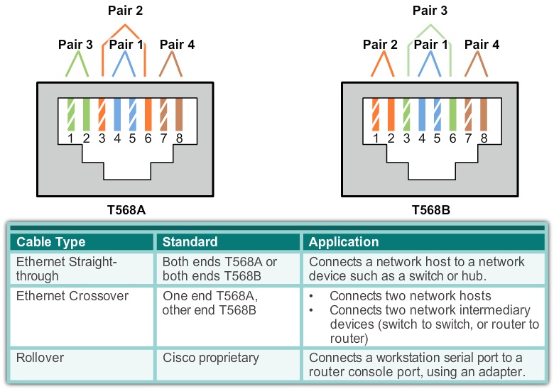
UTP cabling, terminated with RJ-45 connectors, is a common copper-based medium for interconnecting network devices, such as computers, with intermediate devices, such as routers and network switches. Different situations may require UTP cables to be wired according to different wiring conventions. This means that the individual wires in the cable have to be connected in different orders to different sets of pins in the RJ-45 connectors. The following are main cable types that are obtained by using specific wiring conventions:
- Ethernet Straight-through
- Ethernet Crossover
- Rollover
Using a crossover or straight-through cable incorrectly between devices may not damage the devices, but connectivity and communication between the devices will not take place. This is a common error in the lab and checking that the device connections are correct should be the first troubleshooting action if connectivity is not achieved.
Other Copper Cable
Two other types of copper cable are used:
1. Coaxial
2. Shielded Twisted-Pair (STP)
Coaxial Cable
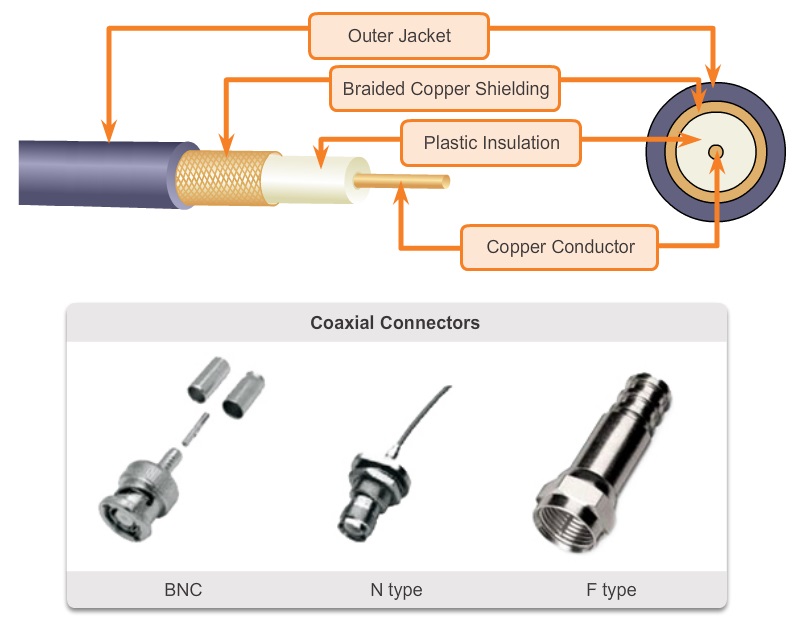
Coaxial cable consists of a copper conductor surrounded by a layer of flexible insulation, as shown in the figure. Over this insulating material is a woven copper braid, or metallic foil, that acts as the second wire in the circuit and as a shield for the inner conductor. This second layer, or shield, also reduces the amount of outside electromagnetic interference. Covering the shield is the cable jacket. All the elements of the coaxial cable encircle the center conductor. Because they all share the same axis, this construction is called coaxial, or coax for short.
Uses of Coaxial Cable
The coaxial cable design has been adapted for different purposes. Coax is an important type of cable that is used in wireless and cable access technologies. Coax cables are used to attach antennas to wireless devices. The coaxial cable carries radio frequency (RF) energy between the antennas and the radio equipment. Coax is also the most widely used media for transporting high radio frequency signals over wire, especially cable television signals. Traditional cable television, exclusively transmitting in one direction, was composed completely of coax cable. Cable service providers are currently converting their one-way systems to two-way systems to provide Internet connectivity to their customers. To provide these services, portions of the coaxial cable and supporting amplification elements are replaced with multi-fiber-optic cable. However, the final connection to the customer’s location and the wiring inside the customer’s premises is still coax cable. This combined use of fiber and coax is referred to as hybrid fiber coax (HFC). In the past, coaxial cable was used in Ethernet installations. Today UTP offers lower costs and higher bandwidth than coaxial and has replaced it as the standard for all Ethernet installations. There are different types of connectors used with coax cable. The figure shows some of these connector types.
Shielded Twisted-Pair (STP) Cable
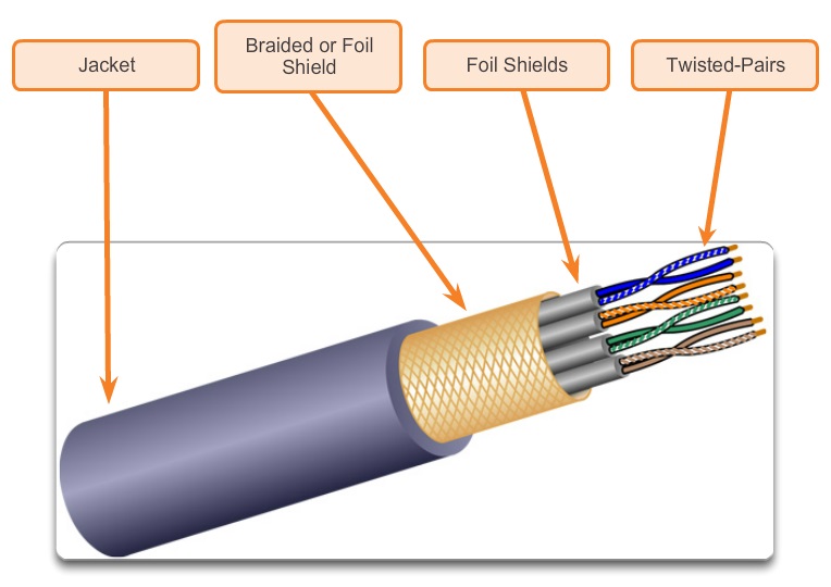
Another type of cabling used in networking is shielded twisted-pair (STP). As shown in the figure, STP uses two pairs of wires that are wrapped in an overall metallic braid or foil. STP cable shields the entire bundle of wires within the cable as well as the individual wire pairs. STP provides better noise protection than UTP cabling, however at a significantly higher price. For many years, STP was the cabling structure specified for use in Token Ring network installations. With the use of Token Ring declining, the demand for shielded twisted-pair cabling has also waned. The new 10 GB standard for Ethernet has a provision for the use of STP cabling. This may provide a renewed interest in shielded twisted-pair cabling.
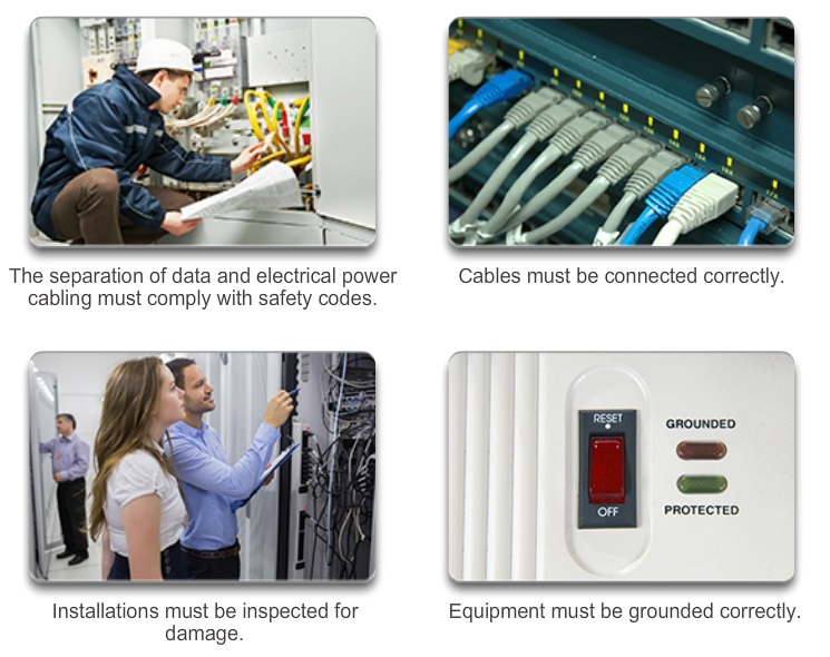
Copper Media Safety
Electrical Hazards
A potential problem with copper media is that the copper wires could conduct electricity in undesirable ways. This could subject personnel and equipment to a range of electrical hazards. A defective network device could conduct currents to the chassis of other network devices. Additionally, network cabling could present undesirable voltage levels when used to connect devices that have power sources with different ground potentials. Such situations are possible when copper cabling is used to connect networks in different buildings or on different floors of buildings that use different power facilities. Finally, copper cabling may conduct voltages caused by lightning strikes to network devices. The result of undesirable voltages and currents can include damage to network devices and connected computers, or injury to personnel. It is important that copper cabling be installed appropriately, and according to the relevant specifications and building codes, in order to avoid potentially dangerous and damaging situations.
Fire Hazards
Cable insulation and sheaths may be flammable or produce toxic fumes when heated or burned. Building authorities or organizations may stipulate related safety standards for cabling and hardware installations.
Fiber Media
Fiber-optic cabling uses either glass or plastic fibers to guide light impulses from source to destination. The bits are encoded on the fiber as light impulses. Optical fiber cabling is capable of very large raw data bandwidth rates. Most current transmission standards have yet to approach the potential bandwidth of this media.
Fiber Compared to Copper Cabling
Given that the fibers used in fiber-optic media are not electrical conductors, the media is immune to electromagnetic interference and will not conduct unwanted electrical currents due to grounding issues. Because optical fibers are thin and have relatively low signal loss, they can be operated at much greater lengths than copper media, without the need for signal regeneration. Some optical fiber Physical layer specifications allow lengths that can reach multiple kilometers.
Optical fiber media implementation issues include:
- More expensive (usually) than copper media over the same distance (but for a higher capacity)
- Different skills and equipment required to terminate and splice the cable infrastructure
- More careful handling than copper media
At present, in most enterprise environments, optical fiber is primarily used as backbone cabling for high-traffic point-to-point connections between data distribution facilities and for the interconnection of buildings in multi-building campuses. Because optical fiber does not conduct electricity and has low signal loss, it is well suited for these uses.
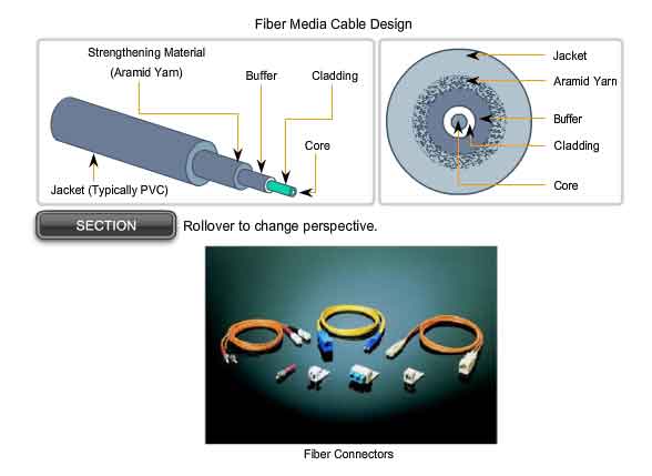
Cable Construction
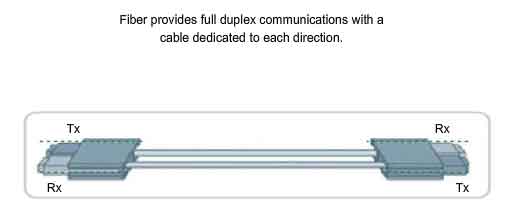
Optical fiber cables consist of a PVC jacket and a series of strengthening materials that surround the optical fiber and its cladding. The cladding surrounds the actual glass or plastic fiber and is designed to prevent light loss from the fiber. Because light can only travel in one direction over optical fiber, two fibers are required to support full duplex operation. Fiber-optic patch cables bundle together two optical fiber cables and terminate them with a pair of standard single fiber connectors. Some fiber connectors accept both the transmitting and receiving fibers in a single connector.
Generating and Detecting the Optical Signal
Either lasers or light emitting diodes (LEDs) generate the light pulses that are used to represent the transmitted data as bits on the media. Electronic semi-conductor devices called photodiodes detect the light pulses and convert them to voltages that can then be reconstructed into data frames.
Note: The laser light transmitted over fiber-optic cabling can damage the human eye. Care must be taken to avoid looking into the end of an active optical fiber.
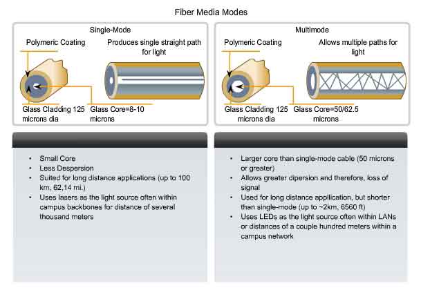
Single-mode and Multimode Fiber
Fiber optic cables can be broadly classified into two types: single-mode and multimode.
Single-mode optical fiber carries a single ray of light, usually emitted from a laser. Because the laser light is uni-directional and travels down the center of the fiber, this type of fiber can transmit optical pulses for very long distances. Multimode fiber typically uses LED emitters that do not create a single coherent light wave. Instead, light from an LED enters the multimode fiber at different angles. Because light entering the fiber at different angles takes different amounts of time to travel down the fiber, long fiber runs may result in the pulses becoming blurred on reception at the receiving end. This effect, known as modal dispersion, limits the length of multimode fiber segments. Multimode fiber, and the LED light source used with it, are cheaper than single-mode fiber and its laser-based emitter technology.
Wireless Media
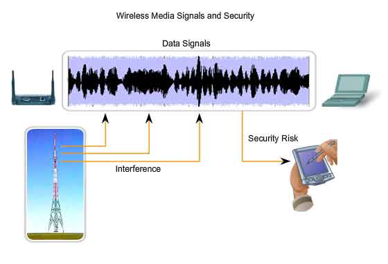
Wireless media carry electromagnetic signals at radio and microwave frequencies that represent the binary digits of data communications. As a networking medium, wireless is not restricted to conductors or pathways, as are copper and fiber media. Wireless data communication technologies work well in open environments. However, certain construction materials used in buildings and structures, and the local terrain, will limit the effective coverage. In addition, wireless is susceptible to interference and can be disrupted by such common devices as household cordless phones, some types of fluorescent lights, microwave ovens, and other wireless communications. Further, because wireless communication coverage requires no access to a physical strand of media, devices and users who are not authorized for access to the network can gain access to the transmission. Therefore, network security is a major component of wireless network administration.
Types of Wireless Networks
The IEEE and telecommunications industry standards for wireless data communications cover both the Data Link and Physical layers. Four common data communications standards that apply to wireless media are:
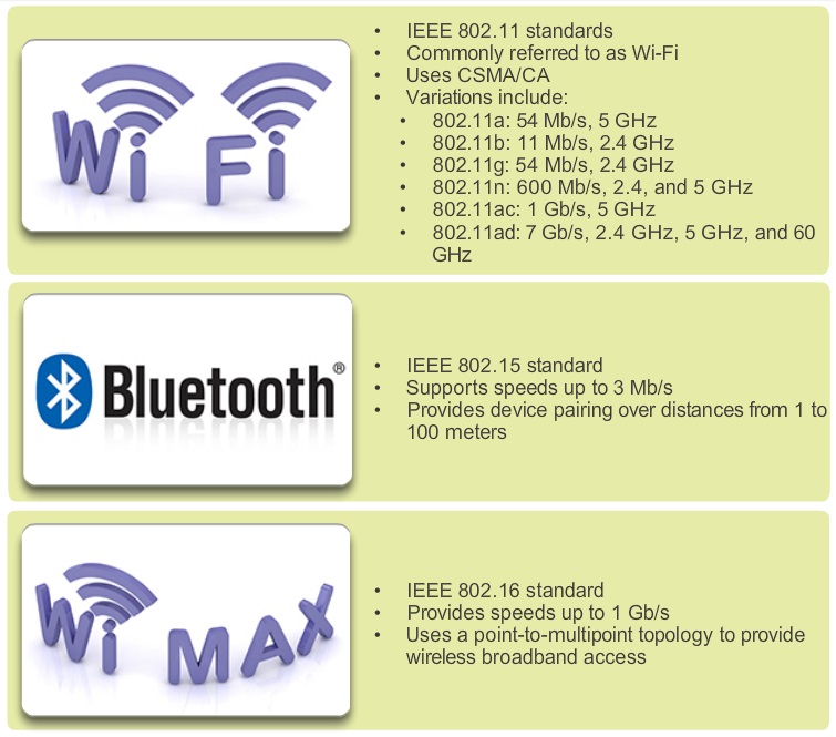
- Standard IEEE 802.11 – Commonly referred to as Wi-Fi, is a Wireless LAN (WLAN) technology that uses a contention or non-deterministic system with a Carrier Sense Multiple Access/Collision Avoidance (CSMA/CA) media access process.
- Standard IEEE 802.15 – Wireless Personal Area Network (WPAN) standard, commonly known as “Bluetooth”, uses a device pairing process to communicate over distances from 1 to 100 meters.
- Standard IEEE 802.16 – Commonly known as WiMAX (Worldwide Interoperability for Microwave Access), uses a point-to-multipoint topology to provide wireless broadband access.
- Global System for Mobile Communications (GSM) – Includes Physical layer specifications that enable the implementation of the Layer 2 General Packet Radio Service (GPRS) protocol to provide data transfer over mobile cellular telephony networks.
Other wireless technologies such as satellite communications provide data network connectivity for locations without another means of connection. Protocols including GPRS enable data to be transferred between earth stations and satellite links. In each of the above examples, Physical layer specifications are applied to areas that include: data to radio signal encoding, frequency and power of transmission, signal reception and decoding requirements, and antenna design and construction.
The Wireless LAN
A common wireless data implementation is enabling devices to wirelessly connect via a LAN. In general, a wireless LAN requires the following network devices:
-
Wireless Access Point (AP) – Concentrates the wireless signals from users and connects, usually through a copper cable, to the existing copper-based network infrastructure such as Ethernet.
- Wireless NIC adapters – Provides wireless communication capability to each network host.
As the technology has developed, a number of WLAN Ethernet-based standards have emerged. Care needs to be taken in purchasing wireless devices to ensure compatibility and interoperability.
Standards include:
IEEE 802.11a – Operates in the 5 GHz frequency band and offers speeds of up to 54 Mbps. Because this standard operates at higher frequencies, it has a smaller coverage area and is less effective at penetrating building structures. Devices operating under this standard are not interoperable with the 802.11b and 802.11g standards described below.
IEEE 802.11b – Operates in the 2.4 GHz frequency band and offers speeds of up to 11 Mbps. Devices implementing this standard have a longer range and are better able to penetrate building structures than devices based on 802.11a.
IEEE 802.11g – Operates in the 2.4 GHz frequency band and offers speeds of up to 54 Mbps. Devices implementing this standard therefore operate at the same radio frequency and range as 802.11b but with the bandwidth of 802.11a.
IEEE 802.11n – The IEEE 802.11n standard is currently in draft form. The proposed standard defines frequency of 2.4 Ghz or 5 GHz. The typical expected data rates are 100 Mbps to 210 Mbps with a distance range of up to 70 meters. The benefits of wireless data communications technologies are evident, especially the savings on costly premises wiring and the convenience of host mobility. However, network administrators need to develop and apply stringent security policies and processes to protect wireless LANs from unauthorized access and damage. These wireless standards and Wireless LAN implementations will be covered in more detail in the LAN Switching and Wireless course.
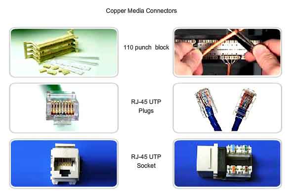
Common Copper Media Connectors
Different Physical layer standards specify the use of different connectors. These standards specify the mechanical dimensions of the connectors and the acceptable electrical properties of each type for the different implementations in which they are employed. Although some connectors may look the same, they may be wired differently according to the Physical layer specification for which they were designed. The ISO 8877 specified RJ-45 connector is used for a range of Physical layer specifications, one of which is Ethernet. Another specification, EIA-TIA 568, describes the wire color codes to pin assignments (pinouts) for Ethernet straight-through and crossover cables. Although many types of copper cables can be purchased pre-made, in some situations, especially in LAN installations, the termination of copper media may be performed onsite. These terminations include crimped connections to terminate Cat5 media with RJ-45 plugs to make patch cables, and the use of punched down connections on 110 patch panels and RJ-45 jacks. The figure shows some of the Ethernet wiring components.
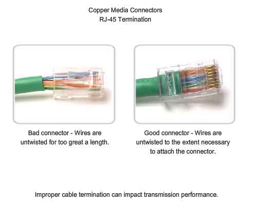
Correct Connector Termination
Each time copper cabling is terminated, there is the possibility of signal loss and the introduction of noise to the communication circuit. Ethernet workplace cabling specifications stipulate the cabling necessary to connect a computer to an active network intermediary device. When terminated improperly, each cable is a potential source of Physical layer performance degradation. It is essential that all copper media terminations be of high quality to ensure optimum performance with current and future network technologies. In some cases, for example in some WAN technologies, if an improperly wired RJ-45-terminated cable is used, damaging voltage levels may be applied between interconnected devices. This type of damage will generally occur when a cable is wired for one Physical layer technology and is used with a different technology.
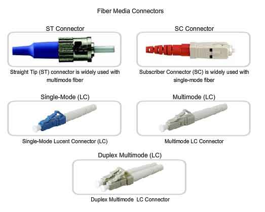
Common Optical Fiber Connectors
Fiber-optic connectors come in a variety of types. The figure shows some of the most common:
Straight-Tip (ST) (trademarked by AT&T) – a very common bayonet style connector widely used with multimode fiber.
Subscriber Connector (SC) – a connector that uses a push-pull mechanism to ensure positive insertion. This connector type is widely used with single-mode fiber. Lucent Connector (LC) – A small connector becoming popular for use with single-mode fiber and also supports multi-mode fiber. Terminating and splicing fiber-optic cabling requires special training and equipment. Incorrect termination of fiber optic media will result in diminished signaling distances or complete transmission failure.
Three common types of fiber-optic termination and splicing errors are:
- Misalignment – the fiber-optic media are not precisely aligned to one another when joined.
- End gap – the media do not completely touch at the splice or connection.
- End finish – the media ends are not well polished or dirt is present at the termination.
It is recommended that an Optical Time Domain Reflectometer (OTDR) be used to test each fiber-optic cable segment. This device injects a test pulse of light into the cable and measures back scatter and reflection of light detected as a function of time. The OTDR will calculate the approximate distance at which these faults are detected along the length of the cable. A field test can be performed by shining a bright flashlight into one end of the fiber while observing the other end of the fiber. If light is visible, then the fiber is capable of passing light. Although this does not ensure the performance of the fiber, it is a quick and inexpensive way to find a broken fiber.
Thanks, If you like this tutorial please share this article to your friends in FB, Twitter,
Related Posts


About The Author
AYYU
I am a blogger since 2010 and I’m the author of this website I'm a systems/network administrator and I enjoy solving complex problems and learning as much as I can about new technologies. I write tutorials based on my work experience and other IT stuff I find interesting. since 2006 in online world also I am a troubleshooter for the well-known website like http://www.fixya.com and many more groups