
Packet Tracer Interface Overview
Cisco Packet Tracer is a fancy e-learning tools are made by Cisco that will simulate the workings of a network based on the topology and configuration imposed by the users exactly like the original. When you open Packet Tracer, by default you will be presented with the following interface:
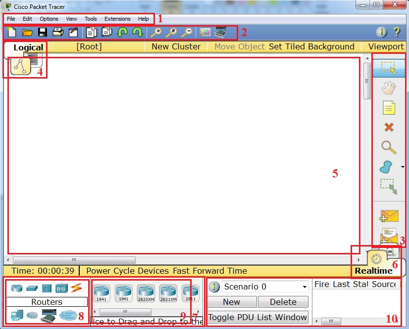
 This initial interface contains ten components. If you are unsure of what a particular interface item does, move your mouse over the item and a help balloon will explain the item.
| 1 | Menu Bar | This bar provides the File, Edit, Options, View, Tools, Extensions, and Help menus. You will find basic commands such as Open, Save, Save as Pkz, Print, and Preferences in these menus. You will also be able to access the Activity Wizard from the Extensions menu. |
| 2 | Main Tool Bar | This bar provides shortcut icons to the File and Edit menu commands. This bar also provides buttons for Copy, Paste, Undo, Redo, Zoom, the Drawing Palette, and the Custom Devices Dialog. On the right, you will also find the Network Information button, which you can use to enter a description for the current network (or any text you wish to include). |
| 3 | Common Tools Bar | This bar provides access to these commonly used workspace tools: Select, Move Layout, Place Note, Delete, Inspect, Resize Shape, Add Simple PDU, and Add Complex PDU. See “Workspace Basics” for more information. |
| 4 | Logical/Physical Workspace and Navigation Bar | You can toggle between the Physical Workspace and the Logical Workspace with the tabs on this bar. In Logical Workspace, this bar also allows you to go back to a previous level in a cluster, create a New Cluster, Move Object, Set Tiled Background, and Viewport. In Physical Workspace, this bar allows you to navigate through physical locations, create a New City, create a New Building, create a New Closet, Move Object, apply a Grid to the background, Set Background, and go to the Working Closet. |
| 5 | Workspace | This area is where you will create your network, watch simulations, and view many kinds of information and statistics. |
| 6 | Realtime/Simulation Bar | You can toggle between Realtime Mode and Simulation Mode with the tabs on this bar. This bar also provides buttons to Power Cycle Devices and Fast Forward Time as well as the Play Control buttons and the Event List toggle button in Simulation Mode. Also, it contains a clock that displays the relative Time in Realtime Mode and Simulation Mode. |
| 7 | Network Component Box | This box is where you choose devices and connections to put into the workspace. It contains the Device-Type Selection Box and the Device-Specific Selection Box. |
| 8 | Device-Type Selection Box | This box contains the type of devices and connections available in Packet Tracer. The Device-Specific Selection Box will change depending on which type of device you choose. |
| 9 | Device-Specific Selection Box | This box is where you choose specifically which devices you want to put in your network and which connections to make. |
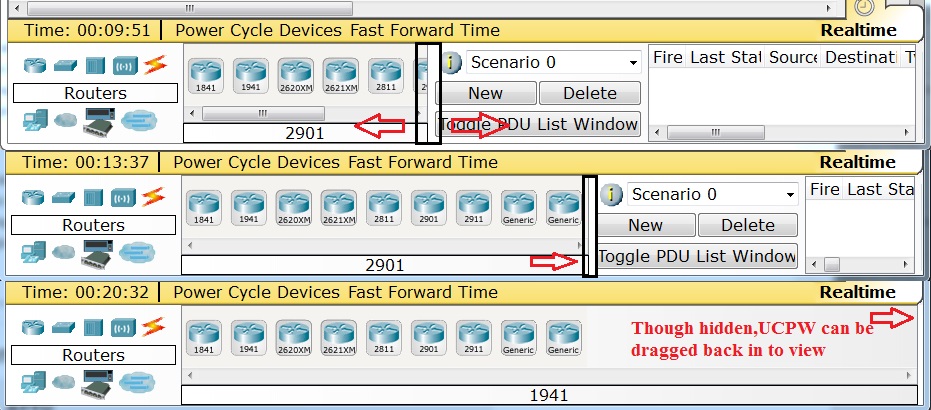
| 10 | User Created Packet Window* | This window manages the packets you put in the network during simulation scenarios. See the “Simulation Mode” section for more details. |
| * You can freely resize the User Created Packet Window (UCPW) by placing the cursor near the left edge of the window (it will turn into a “resize” cursor) and then drag the cursor left or right. You can hide the window from view by dragging the edge all the way to the right. When the UCPW is hidden, you can bring it back by placing the cursor on the edge (notice when the resize cursor appears) and then dragging the edge back. |
Workspaces and Modes
Packet Tracer has two workspaces (Logical and Physical) and two modes (Realtime and Simulation). Upon startup, you are in the Logical Workspace in Realtime Mode. You can build your network and see it run in real time in this configuration. You can switch to Simulation Mode to run controlled networking scenarios. You can also switch to the Physical Workspace to arrange the physical aspects (such as the location) of your devices. Note that you view a simulation while you are in the Physical Workspace. You should return to the Logical Workspace after you are done in the Physical Workspace.
Setting Preferences
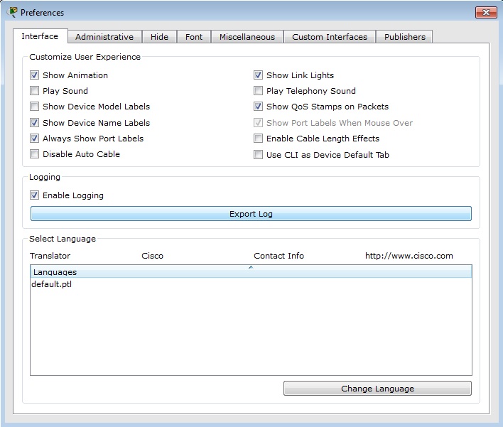
You can customize your Packet Tracer experience by setting your own preferences. From the Menu Bar, select Options > Preferences (or simply press Ctrl + R) to view the program settings.
Under the Interface panel, you can toggle the Animation, Sound, and Show Link Lights settings to suit the performance of your system and your preferences. You can also manage information clutter with the Show Device Labels, Always Show Port Labels, and Show Port Labels When Mouse Over settings. Also, you can also toggle Show QoS Stamps on Packets shown in Simulation Mode and Enable Cable Length Effects. The Enable Auto Cable option allows you to toggle the Automatic Connection when connecting devices. The Show Device Dialog Taskbar option allows you to toggle the taskbar that is displayed at the bottom of the workspace which organizes currently opened device dialogs. The Logging feature allows the program to capture all Cisco IOS commands that you enter and export them to a text file (refer to the “Configuring Devices” page for more information). The Simulation – Buffer Full Action feature allows you to set the preferred action that Packet Tracer will perform. You can set the action to Prompt if you want to be prompted when the Simulation buffer is full. At the prompt, you can either Clear Event List or View Previous Events. Alternatively, you can set the action to either Auto Clear Event List to allow Packet Tracer to automatically clear the Event List when the buffer is full or you can set the action to Auto View Previous Events to automatically view the previous events. The Enable Screen Reader Support accessibility feature reads out all the titles and descriptions of the visible window that has the focus. Lastly, you can also change the base language of the program by choosing from the Languages list and then pressing the Change Language button.
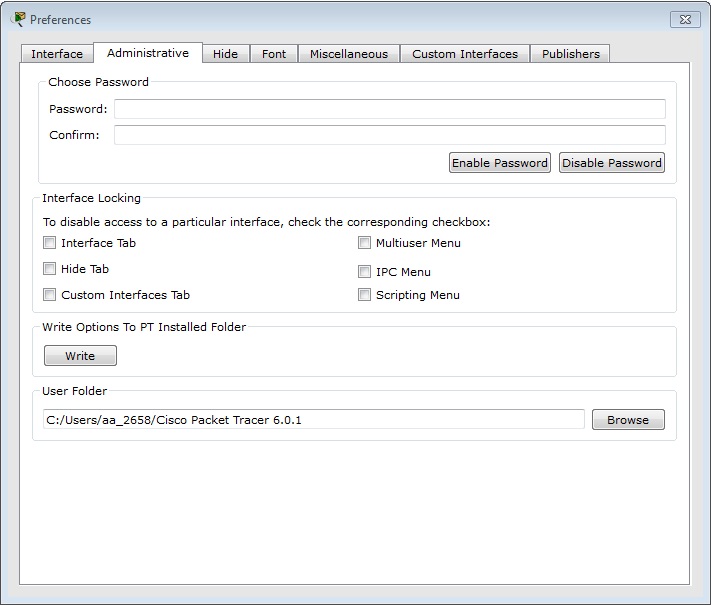
 Under the Administrative panel, you can disable access to a particular interface such as the Interface tab and the Multiuser menu using the Interface Locking feature. In order settings and configurations to apply globally for every user on the machine, you need to click on the Write button to save the PT.conf file to the Packet Tracer installation folder. Optionally, you may change the User Folder to a different location which is where your own settings, configurations, save files, and device templates are stored. Additionally, you can set a Password to prevent others from tampering with these preferences. Note that the password is case-sensitive.
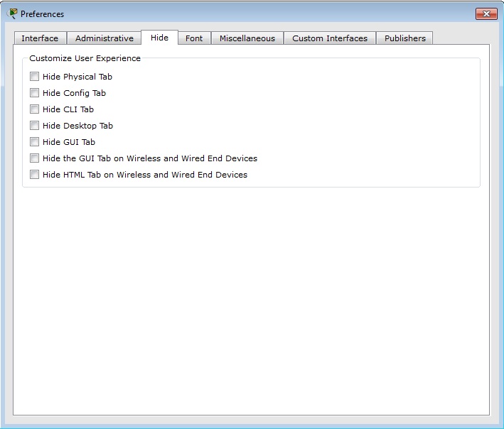
 Under the Hide panel, you can choose to hide or show the Physical, Config, CLI, Desktop, GUI, HTML GUI, and HTML tabs in the device edit dialog.
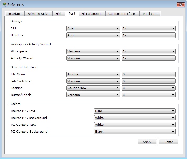
 Under the Font panel, you can select different fonts and font sizes for the Dialogs, Workspace/Activity Wizard, and the General Interface Under the Colors category, you can change the font color of the Router IOS Text, Router IOS Background, PC Console Text, and PC Console Background.
 Setting a User Profile
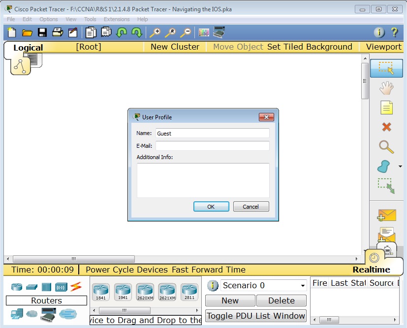
You can set your user profile for activity assessment and Multiuser identification. From the Menu Bar, select Options > User Profile to view the User Profile dialog. In the User Profile dialog, you can enter your Name, E-Mail, and any Additional Info about yourself that you may want to share.
 Algorithm Settings
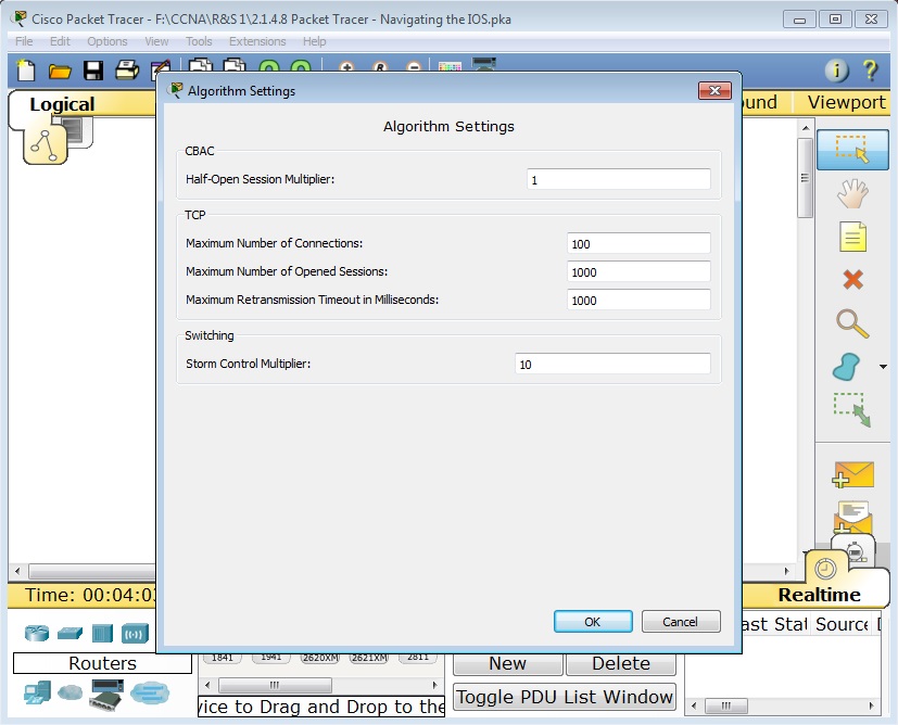
The Algorithms Settings dialog allows the user to make configurations that are otherwise not available in IOS. It also allows tweaking of algorithm settings to make visualization of certain algorithm/protocol behaviors more easily viewable.
CBAC Half-Open Session Multiplier: If the number of half-open CBAC sessions multiplied by this number exceeds the configured max half-open session count, new sessions would not be opened.
TCP Maximum Number of Connections: If the number of connections in SYN-RECEIVED state exceeds this number, any new connections would be rejected.
TCP Maximum Number of Opened Sessions: If the number of connections exceeds this number, any new connections would be rejected.
TCP Maximum Retransmission Timeout in Milliseconds : If a TCP connection does not receive an acknowledgement to a segment it transmitted in this number, it would retransmit the segment.
Switching Storm Control Multiplier: If the bandwidth percentage of broadcast frames used multiplied by this number exceeds the configured threshold, the broadcast frame would be dropped.
 Saving a PKZ
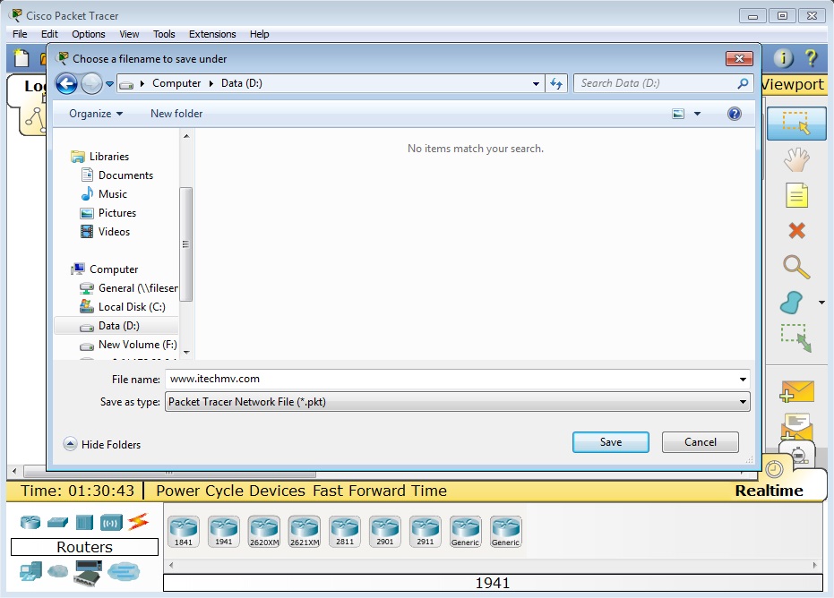
Packet Tracer allows you to save your topology (PKT) as well as any custom device icons and backgrounds that you applied to on the Logical Workspace and Physical Workspace to a save file called a PKZ. A PKZ is able to retain any external files you add in a single save file, which allows for portability and compactness from computer to computer. To create a PKZ, go to File > Save as Pkz. Enter a file name for the PKZ and click on Save. In the Pkz Select Files dialog, you will be able to add and remove files that you want to save along with PKT. To add a file, click on the Add button and browse to the file you want to add then click Open. To remove a file, select the file from the list then click Remove. Once you are done adding and removing files, click OK to create the PKZ file.
Thanks, If you like this tutorial please share this article to your friends in FB, Twitter,

Related Posts


About The Author
AYYU
I am a blogger since 2010 and I’m the author of this website I'm a systems/network administrator and I enjoy solving complex problems and learning as much as I can about new technologies. I write tutorials based on my work experience and other IT stuff I find interesting. since 2006 in online world also I am a troubleshooter for the well-known website like http://www.fixya.com and many more groups